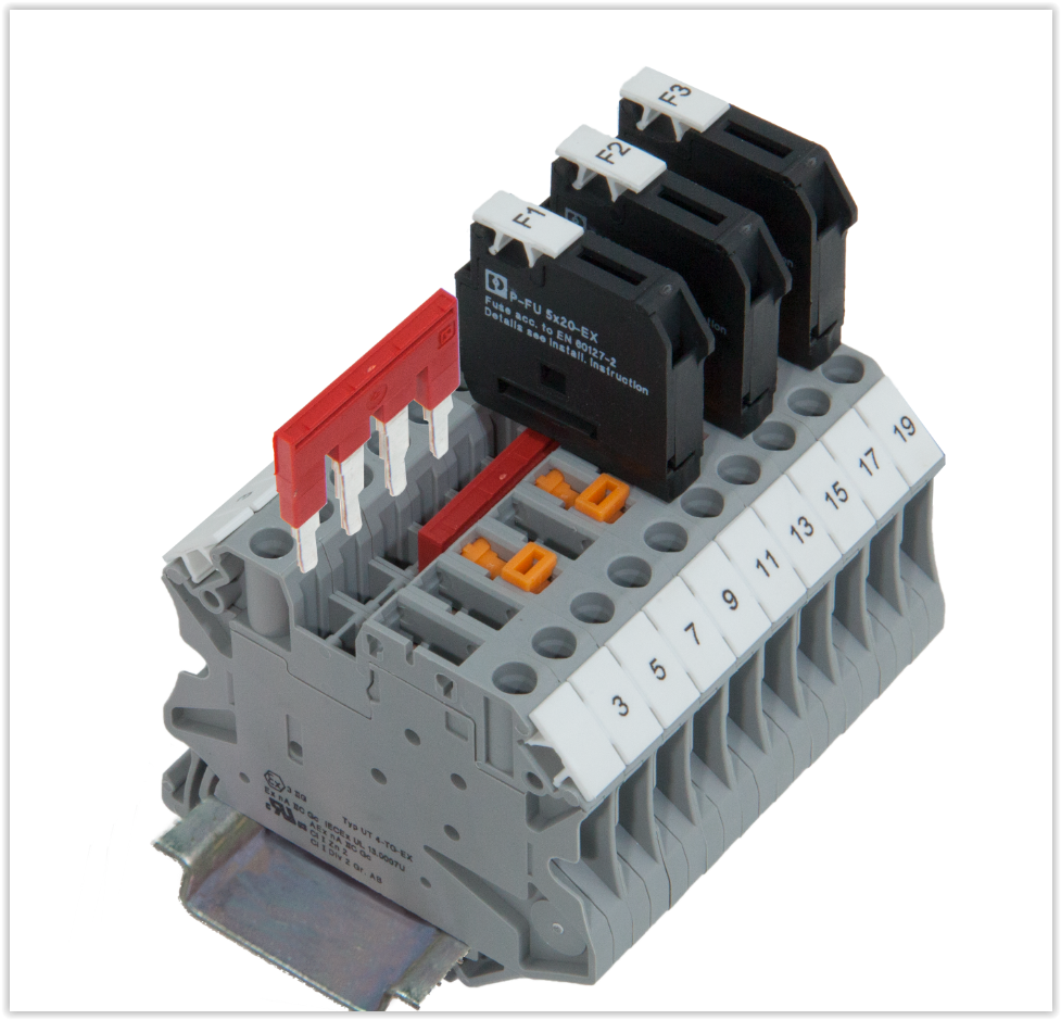

Each terminal block will generally be able to accept a flexible range of wire sizes, for example, 26~12 AWG.

Wire Size/Type: To ensure wires will physically fit into the terminal block housing, terminal blocks list the size or gauge of wire that the module can accept, which is specified in units of American wire gauge (AWG) in North America.

Pitch is determined by the terminal block’s overall rating where factors like creepage, voltage/current, and clearance are concerned. Pitch: Defined as the center distance from pole to pole, the pitch is represented in values such as 2.54 mm, 3.81 mm, 5.0 mm, and so on. Terminal blocks usually offer pole counts from a single-pole up to as many as 24 poles. Pole Count: The pole count is used to specify the number of individual circuits that the terminal block will house based on the application need. The voltage rating is partially determined by the dielectric strength and pitch of the terminal block housing. Voltage rating: Like the current rating, a terminal block’s voltage rating must be greater than the maximum system voltage and should also take into account any voltage surges that may be present in the end system. In general, it is recommended to select a terminal block with a current rating of at least 150% of the system’s expected max current. Overheating and damage to a terminal block can occur when operating at too high of a current, which can present critical safety concerns. They are as follows:Ĭurrent rating: Typically, the most crucial specification to consider in terminal block designs, current rating is based on three areas: the conductivity of the terminals, cross-sectional area, and the corresponding heat rise.

Feed-through terminal blocks, similar to PCB mount types, are available in single, dual, or multi-row modules.Īlthough an engineer will likely know their overall system voltage and current requirements when implementing a terminal block, there are still other factors that are important to note during the design phase. Lastly, utilized for wire-to-wire connections, feed-through terminal blocks contain one input and one output contact where two separate wires are inserted into opposite sides of the housing to connect the two wires together. Barrier strips are also offered in multiple configurations including single or double row. The wire is simply placed onto the screw and tightened into the housing for a secure connection. They feature a screw down terminal that can accept either a bare wire or a wire that has a ring or spade attached to its end. Also referred to as Eurostyle terminal blocks, they can be found in single-, dual-, or multi-row configurations.īarrier strips are often used where vibration is a factor. This housing is then soldered to a PCB, which is why they are commonly called wire-to-board terminal blocks. PCB mount terminal blocks operate by inserting bare wires into the module where a clamp secures the wire in the housing. Three of the most common terminal block types used in designs are PCB mount, barrier strips, and feed-through. This article will cover topics including key electrical and mechanical considerations, safety ratings, and more in greater detail to aid engineers in the selection process. Also known as screw terminals, terminal connectors, or connection terminals, terminal blocks offer engineers semi-permanent wire connections that provide organized and simplified inspection or repair capabilities in the field.Īlthough a widely used component in numerous applications, it is still important to have a basic understanding of common terminal block types and specifications before making a final selection. Consisting of a modular housing and insulated body, terminal blocks are used to secure two or more wires together in electrical systems in need of safe connections.


 0 kommentar(er)
